Main Screen
Important
Make sure the PCASpy tutorial server is running
This will be the main piece of our Beam Positioning application and will group the other components of this tutorial.
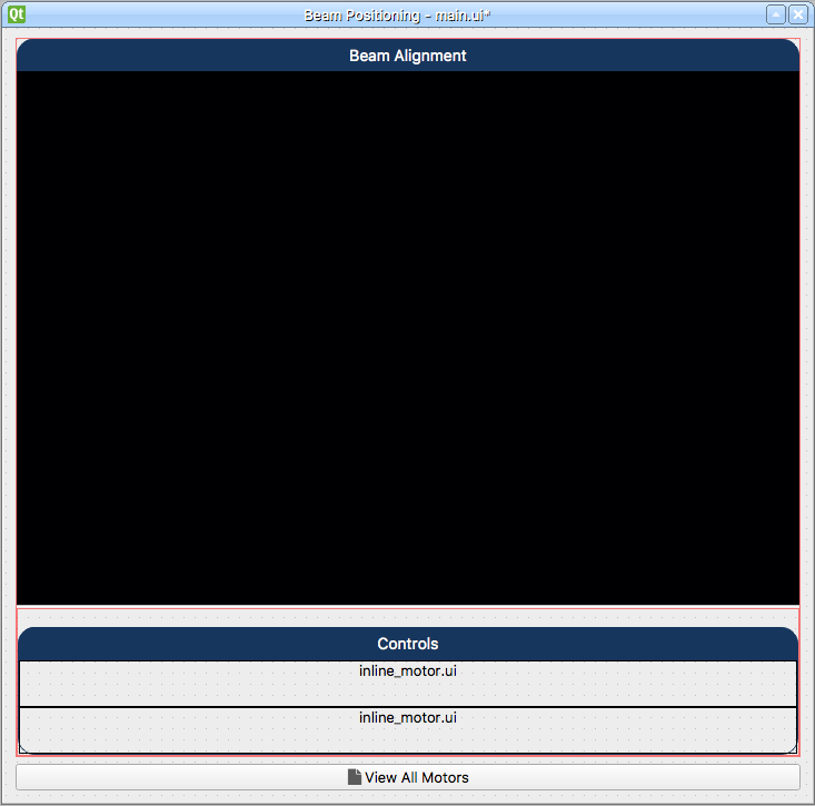
The finished result will look like this:
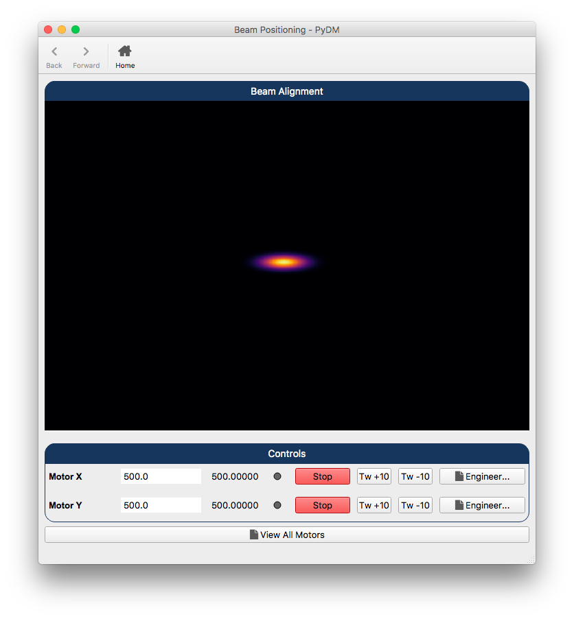
Main Screen for Beam Positioning Application
Step 1.
Let’s start by opening the Qt Designer and creating a new
Widget.
Step 2.
With the new form available, let’s add a
Vertical Layoutwidget and make it fill the whole form. Let’s selectLayout Verticallyfor the Form.
Step 3.
Now that we have a layout, let’s take a look at the widgets on this screen:
Step 3.1.
The first
Labelwill be the title of our screen:Drag and drop a
Labelinto the previously addedVertical Layout.Set the
textproperty of this label to:Beam Alignment.In order to make the label look better as a title, add the following to the
stylesheetproperty:QLabel { qproperty-alignment: AlignCenter; border: 1px solid #FF17365D; border-top-left-radius: 15px; border-top-right-radius: 15px; background-color: #FF17365D; padding: 5px 0px; color: rgb(255, 255, 255); max-height: 25px; font-size: 14px; }
Step 3.2.
The second widget that we will add is a
PyDMImageView, which will display the image coming from our camera:Drag and drop a
PyDMImageViewinto the previously addedVertical Layoutunder theLabelthat was added at Step 3.1.Set the
objectNameproperty toimageView.Set the
imageChannelproperty toca://IOC:Image.Set the
widthChannelproperty toca://IOC:ImageWidth.Set the
readingOrderproperty toClike.Set the
maxRedrawRateproperty to30so we can update the image at 30 Hz.
Step 3.3.
The third widget that we will add is a
Vertical Layout, which will be the placeholder for the controls area of the screen:Drag and drop a
Vertical Layoutinto the previously addedVertical Layoutunder thePyDMImageViewthat was added at Step 3.2.
Step 3.4.
The fourth widget that we will add is a
Label, which will be updated with the result of the calculation of beam position in the next section (Adding Code into the Main Display):Drag and drop a
Labelinto theVertical Layoutthat was added in Step 3.3.Set the
objectNameproperty of this widget tolbl_blobs.Important
It is very important to set the
objectNameproperty of widgets in the designer if you intend to access them using code, otherwise the names will be automatically assigned, and will not make much sense later on.Set the
textproperty to empty so this label will only show information when we write to it using the code later on.
Step 3.5.
The fifth widget that we will add is another
Label, which will show the title of our controls area:Drag and drop a
Labelinto theVertical Layoutthat was added in Step 3.3 right under theLabeladded in Step 3.5.Set the
textproperty of this label to:Controls.In order to make the label look better as a title, add the following to the
stylesheetproperty:QLabel { qproperty-alignment: AlignCenter; border: 1px solid #FF17365D; border-top-left-radius: 15px; border-top-right-radius: 15px; background-color: #FF17365D; padding: 5px 0px; color: rgb(255, 255, 255); max-height: 25px; font-size: 14px; }
Step 3.6.
The sixth widget that we will add is a
Frame, which will be the container for our two motors’Embedded Displays:Drag and drop a
Frameunder theLabeladded in Step 3.6.Set the
frameShapeproperty toStyledPanel.Set the
frameShadowproperty toRaisedSet the
stylesheetproperty to:QFrame#frame{ border: 1px solid #FF17365D; border-bottom-left-radius: 15px; border-bottom-right-radius: 15px; }
Step 3.7.
The seventh widget that we will add is a
PyDMEmbeddedDisplay, which will display theinline_motor.uiwith information for our first motor axis:Drag and drop a
PyDMEmbeddedDisplayinto theFrameadded in Step 3.7.Right-click the
Framefrom Step 3.7 and selectLayout >> Layout Vertically.Set the
macrosproperty to{"MOTOR":"IOC:m1"}.Set the
filenameproperty toinline_motor.ui.
Step 3.8.
The eighth widget that we will add is a
PyDMEmbeddedDisplay, which will display theinline_motor.uiwith information for our second motor axis:Drag and drop a
PyDMEmbeddedDisplayinto theFrameadded in Step 3.7.Set the
macrosproperty to{"MOTOR":"IOC:m2"}.Set the
filenameproperty toinline_motor.ui.
Step 3.9.
Finally, the ninth widget that we will add is a
PyDMRelatedDisplayButton, which will open theAll Motorsscreen that will be developed later:Drag and drop a
PyDMRelatedDisplayButtoninto theVertical Layoutadded in Step 2.Add the string
all_motors.pyto thefilenamesproperty.Uncheck the
openInNewWindowproperty.Set the
textproperty to:View All Motors
Step 3.10.
Once all the widgets are added to the form, it is now time to adjust the layouts and make sure that all is well positioned and behaving nicely.
Using the
Object Inspectorat the top-right corner of the Qt Designer window, select theframeobject and set the properties according to the table below:Property
Value
layoutLeftMargin
0
layoutTopMargin
0
layoutRightMargin
0
layoutBottomMargin
0
layoutSpacing
0
Continuing with the
Object Inspector, select thevertical layoutobject right before theframeand set the properties according to the table below:Property
Value
layoutSpacing
0
Still with the
Object Inspector, now select the top mostverticalLayoutobject set the properties according to the table below:Property
Value
layoutSpacing
0
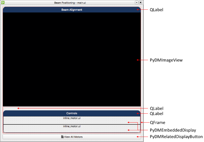
The end result will be something like this:
Step 4.
Save this file as
main.ui.Warning
For this tutorial it is important to use this file name, as it will be referenced at the other sections. If you change it please remember to also change at the next steps when referenced.
Step 5.
Test the Expert Motor Screen:
pydm main.ui
Note
Purple borders will appear around any widgets that have “Alarm Sensitive Border” enabled. These can be removed by simply unchecking the setting. (for the purposes of this tutorial, these borders are not significant and can be in either the on or off state)
Note
You can download this file using this link.