Omega3P command syntax
Block-by-block description of the .omega3p input file. Each block is shown as a complete example followed by the meaning of every key. Narrative explanations and worked cases are in the Omega3P module guide; the machine-generated list of every keyword the code reads, with defaults and source locations, is in the Omega3P keyword table.
Top-level blocks: ModelInfo, FiniteElement, PRegion, EigenSolver, Port, PostProcess.
ModelInfo
ModelInfo : {
  File: ./pillbox+recWG4.ncdf
  BoundaryCondition : {
    Magnetic:  1, 2
    Electric:  3, 4
    Exterior:  6
    Waveguide: 7
  }
  SurfaceMaterial : {
    ReferenceNumber: 6
    Sigma: 5.8e7
  }
  Material : {
    Attribute: 1
    Epsilon:   1.0
    Mu:        1.0
  }
}
File: mesh in NetCDF format, with an optional path. Default directory is where the job was submitted.
BoundaryCondition: maps boundary types to the sideset numbers assigned in Cubit. Every surface must belong to exactly one.
| Type | Meaning |
|---|---|
Electric |
Tangential E = 0. Perfect conductor or electric symmetry plane. |
Magnetic |
Tangential H = 0. Magnetic symmetry plane. |
Exterior |
Computationally identical to Electric, but marks a real metal wall so that wall loss and Q0 are computed by perturbation using the conductivity in SurfaceMaterial. |
Impedance |
Fields related by a surface impedance from the conductivity in SurfaceMaterial. For a lossy conductor when the skin depth is small compared with the element size. Requires FrequencyShift to be close to the mode frequency, since the impedance is evaluated there. |
Absorbing |
First-order absorbing boundary for waves at c. For coaxial ports and beam pipe truncation. See Port with CutoffFrequency. |
Waveguide |
Modal waveguide boundary. Pair with a Port block. |
Periodic_M, Periodic_S |
Master and slave surfaces of a periodic boundary. Their surface meshes must be identical. |
Theta |
Phase advance in degrees between master and slave. |
SurfaceMaterial: wall properties for loss calculation. ReferenceNumber is the sideset; Sigma the conductivity in S/m. Absent, the wall is copper at 5.8×10⁷ S/m. Repeat the block for surfaces of different materials.
Material: volume properties by Cubit block. Absent, the volume is vacuum.
| Key | Meaning |
|---|---|
Attribute |
Block ID |
Epsilon, Mu |
Relative permittivity and permeability |
EpsilonImag, MuImag |
Imaginary parts for material loss. Default 0. Negative for a passive lossy material. |
PML |
Sub-block making this block a perfectly matched layer, below |
PML
A perfectly matched layer terminates a domain by absorbing outgoing waves in an artificially lossy region. The conductivity ramps from zero at the inner face to a maximum at the outer face:

where \(d\) is the layer thickness, \(m\) the polynomial order, \(R\) the desired reflection coefficient, and \(\eta_0\) the free-space impedance. Give either Reflection Coefficient, from which the maximum is computed, or Maximum Sigma directly.
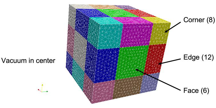
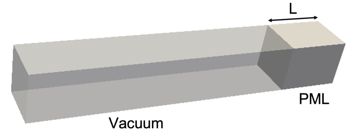
Free-space termination needs face, edge, and corner layers; a waveguide termination needs one face layer.
Material : {
  Attribute: 2
  PML: {
    Type: Face
    Start: -0.01143 -0.00508 0.08       // bounding box of the layer, m
    End:    0.01143  0.00508 0.10
    Direction: 0. 0. +1.                // outward normal
    Reflection Coefficient: 1.e-5
    Polynomial Order: 2
    Maximum Sigma: 2.e0 2.e0 2.e0       // alternative to Reflection Coefficient
  }
}
| Key | Meaning |
|---|---|
Type |
Face (6 orientations), Edge (12), or Corner (8); a spherical PML may also be centred on a shifted origin (new since CW23) |
Start, End |
Bounding box of the layer in m |
Direction |
Orientation: one nonzero component for Face, two for Edge, three for Corner, each ±1 |
Reflection Coefficient |
Target reflection; sets Maximum Sigma |
Maximum Sigma |
Conductivity in x, y, z in S/m, if not derived from the reflection coefficient |
Polynomial Order |
\(m\) in the profile |
A spherical or cylindrical PML replaces the bounding box and direction with the layer geometry:
PML: {
  Type: Face
  SubType: Sphere            // or Cylinder
  BoundaryID: 6              // sideset of the outer surface
  Radius: 0.05
  Thickness: 0.004
  Reflection Coefficient: 1.e-5
  Polynomial Order: 2
}
Plasma material
New since CW23
A Material may carry a Plasma block instead of fixed Epsilon and Sigma. The permittivity and conductivity are then evaluated point by point from an electron density and collision frequency given as expressions in x, y, z (metres). Available in Omega3P and S3P.
Material : {
  Attribute: 2
  Plasma : {
    Type:            Ionosphere          // the only model so far
    Frequency:       1.0e7               // Hz, used to evaluate eps(omega)
    ReferenceHeight: 3.0e5               // m, Ionosphere profile parameter
    Sharpness:       1.0e4               // m, Ionosphere profile parameter
    Density:         "1e11*exp(-(z-3e5)/1e4)"   // electrons per m^3, expression in x y z
    CollisionFreq:   "1e3"               // 1/s, expression; default 0
    Epsilon:         "1"                 // background relative permittivity, expression; default 1
    Sigma:           "0"                 // extra conductivity, S/m, expression; default 0
  }
}
Type, Frequency, ReferenceHeight and Sharpness are required for Ionosphere. The permittivity follows the cold-plasma form 1 minus omega_p^2 over (nu^2 plus omega^2) with the plasma frequency computed from Density. Expressions use the exprtk syntax: + - * /, ^, exp, sin, sqrt, and the variables x, y, z.
FiniteElement
Order is the polynomial order of the basis functions, 1 to 6; 2 is adequate for most work. CurvedSurfaces (also accepted as Curved Surfaces) uses the mid-edge nodes of the quadratic mesh to represent curved boundaries; default on.
PRegion
Different orders in different blocks. Set the global order to 0 and give each block its own:
FiniteElement : { Order: 0  CurvedSurfaces: on }
PRegion : { Type: Material  Reference: 1  Order: 2 }
PRegion : { Type: Material  Reference: 2  Order: 3 }
Reference is the block ID. Every block must then appear in a PRegion.
EigenSolver
| Key | Default | Meaning |
|---|---|---|
NumEigenvalues |
1 | Modes to find, counting upward from FrequencyShift |
FrequencyShift |
10 GHz | Modes above this frequency are searched. Set just below the lowest mode of interest. |
Tolerance |
1e-8 | Relative eigenpair residual |
MaxIterations |
200 | Krylov iteration limit |
The default solver handles real (lossless) and complex (lossy or port-loaded) problems as linear or quadratic eigenproblems. A port-loaded problem stays quadratic only when every loaded port mode shares the same cutoff frequency. Otherwise use the nonlinear solver below.
Linear solver inside the eigensolver
New since CW23
PETSc Krylov solvers with ACE3P's multilevel (MP) preconditioner inside the eigensolver, and the complex-PETSc build for lossy and periodic problems, were added in 2026 (v2026.11).
The shift-invert operator inside each Arnoldi iteration can use PETSc instead of the default direct solver, which matters for problems too large for MUMPS:
EigenSolver : {
  NumEigenvalues: 1
  FrequencyShift: 1.0e9
  Arnoldi: {
    LinearSolver: {
      Solver: PETSc
      Preconditioner: MP         // p-order multilevel preconditioner
      SubCommSize: 8
      Tolerance: 1e-10
      MaxIterations: 8000
      PETScOption: {
        Runtime: -ksp_type cg -log_view -options_left -ksp_converged_reason
      }
    }
  }
}
| Key | Default | Meaning |
|---|---|---|
Solver |
MUMPS | PETSc to use a PETSc Krylov solver |
Preconditioner |
PETSc built-in | MP: ACE3P's multilevel preconditioner, which solves at order 1 to precondition order 2 |
SubCommSize |
8 | MPI sub-communicator size for MP |
Tolerance |
1e-16 | Relative convergence |
MaxIterations |
1000 | Krylov iteration cap |
PETScOption.Runtime |
PETSc command-line options; several Runtime lines allowed |
Use -ksp_type cg for lossless (Hermitian) problems and -ksp_type gmres for lossy (non-Hermitian) ones; CG diverges on the latter. Complex problems need the binaries built against complex PETSc, in the bin-petsc-complex directory of the installation. The same LinearSolver nesting applies inside ESIL, InvertMode, and the other eigensolver containers.
Nonlinear eigensolver (CORK)
EigenSolver : {
  NumEigenvalues: 3
  Tolerance:      1e-10
  FrequencyShift: 1.0e9
  SolverMode:     CORK
  CORK: {
    TargetFrequencyMin:  1.0e9
    TargetFrequencyMax:  2.4e9
    TargetFrequencyImag: 5.0e8
    MaxIterations:       500
    ApproxTolerance:     1e-12
    ApproxMaxDegree:     100
    OneRKSShift:         1
  }
}
| Key | Meaning |
|---|---|
TargetFrequencyMin, TargetFrequencyMax |
Real-frequency search window in Hz |
TargetFrequencyImag |
Largest imaginary part searched, Hz |
MaxIterations |
Nonlinear iteration cap |
ApproxTolerance |
Accuracy of the rational approximation |
ApproxMaxDegree |
Maximum polynomial degree of the approximation |
OneRKSShift |
Use a single rational Krylov shift. Read by CORK_RationalNewton.C; present in the CW23 example but not described in the command reference. |
Procedure: run once loading many modes per port, read the cutoffs in 2dports.log, count the propagating modes at each port for the modes of interest, and rerun loading only those. Tutorial 2 walks through it.
MUMPS
New since CW23
Optional top-level MUMPS block, read by every module that factorizes with MUMPS (Omega3P, S3P, T3P, Pic3P, TEM3P, Gun3P). Since v2026.11 a factorization that runs out of workspace (MUMPS error -9) is retried automatically with a doubled memory margin, 45 to 90 to 180 to 200 percent, instead of aborting. The block tunes that behaviour; without it only the retry is active.
MUMPS : {
  MemoryRelaxation:    90      // starting margin, percent (default 45)
  MaxMemoryRelaxation: 200     // stop retrying above this (default 200)
  MemoryPerRank:       14000   // optional cap on workspace per rank, MB
  ICNTL_35: 1                  // any raw MUMPS ICNTL(k), applied last
}
If a log shows a retry line, set MemoryRelaxation to the value that succeeded to skip the wasted first attempt. Results do not depend on the margin.
Port
One block per Waveguide surface. Absent, one mode is loaded. ReferenceNumber must match the sideset listed under Waveguide.
For an Absorbing surface, a Port block with CutoffFrequency improves the first-order boundary by giving it the guide's phase velocity at the eigenfrequency instead of c:
PostProcess
| Key | Default | Meaning |
|---|---|---|
Toggle |
on | Write .mod field files for ParaView |
ModeFile |
omega3p |
Prefix of the mode files |
WriteLoss |
off | Also write .loss files with the surface power density distribution. Read as PostProcess.WriteLoss in the shared post-processor emfem/src/NewPP.C. |
Post-processing of modes for R/Q, kick factors, and field extraction is done by acdtool postprocess rf; see the acdtool command syntax.